Ethernet Multilogger - universal datalogger with 4 inputs
Battery powered datalogger with 4 universal inputs for measurement of 0-10V voltage, 0-20mA current, two-state signal and for counting pulses.
Signals are connected to four detachable terminal blocks.
Multilogger can be installed permanently to Ethernet network or work as portable device.
Included is traceable calibration certificate in accordance with EN ISO/IEC17025.
The Multilogger is a battery operated datalogger capable of measuring and recording sensor and electrical values through its Inputs.
Datalogger can be connected to Ethernet. Then measured values can be viewed on a web browser, as well as stored and downloaded for later analysis.

-
codeM1300
-
Warranty3 years
Technical data
Measured value
DC CURRENT
BINARY SIGNAL
COUNTER INPUT
GENERAL TECHNICAL DATA
cyclic - after filling memory oldest data is overwritten by new
Features
Up to 4 physical Inputs - TERMINALS
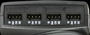
- Sensors with voltage output (range 0-10 V; accuracy ±10 mV)
- Sensors with current output (range 0-20 mA; accuracy ±20 µA)
- Sevices with two-state output (potential-less contact or voltage signal 0-30V); may be applied to input 3 and 4
- Devices with pulse signal (potential-less contact or voltage signal 0-30V); may be applied to input 4
Evaluation of up to 16 variables
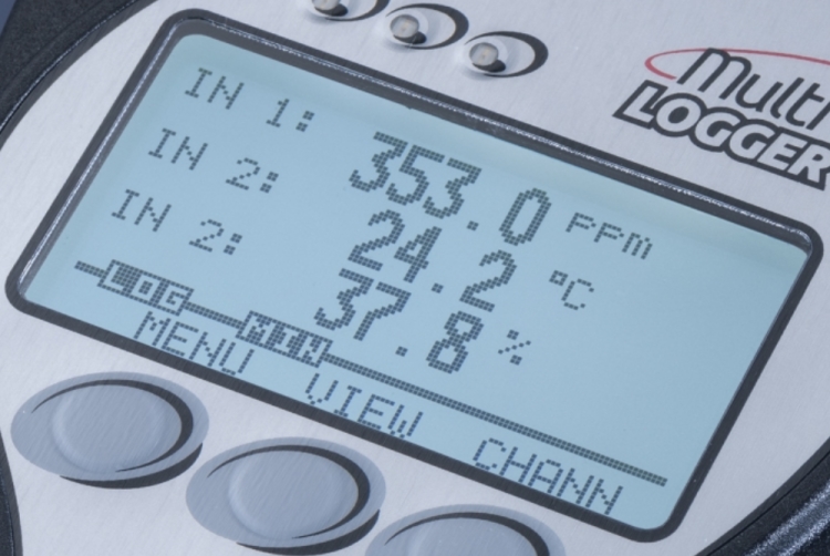
The measured values are stored in the internal non-volatile memory. Memory capacity is up to 1 million values. Logging mode can be adjusted as non-cyclic, when logging stops after filling the memory, or cyclic, when after fulfilling the memory oldest stored values are overwritten by new ones.
Measured values are displayed on the screen with backlight option and the ability to change the size of display digits
Power supply
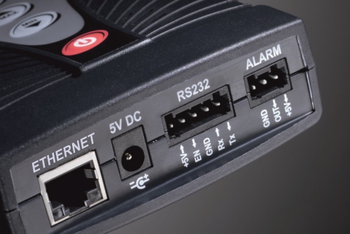
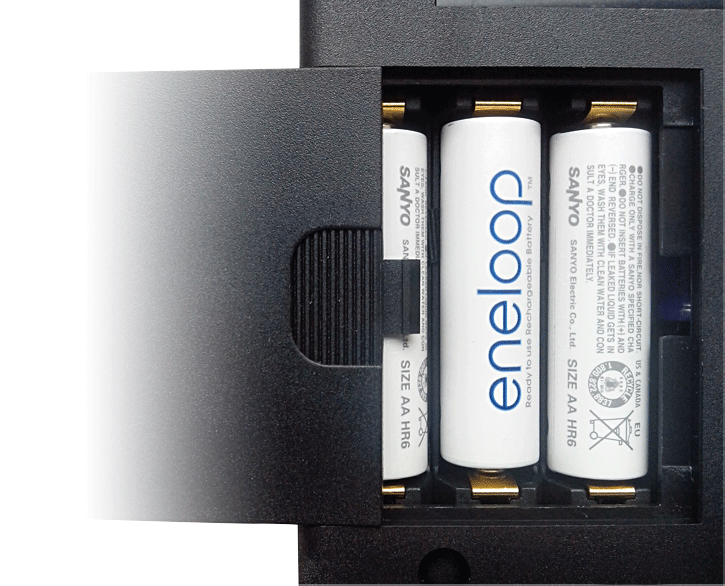
Multilogger can be powered by AC adapter or by rechargeable batteries with charging capability. Batteries are always a part of the device (you can also use standard alkaline AA batteries). Batteries power the device for several months.
While using the AC adapter, the batteries provide backup operations and provide recording and measurement during power failure. Thanks to the Ethernet output the device informs about the failure via e-mail message.
Alarm limits and alarm indication
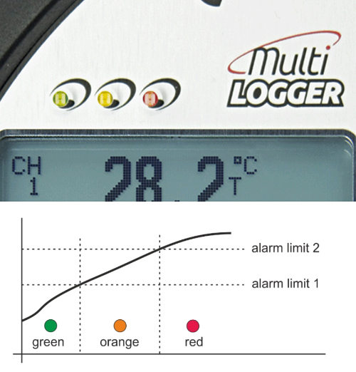
It is possible to set two independent alarm limits for each channel (i.e. measured or calculated value).
Alarm signalization can be acoustic (built-in beeper), optical, sending an e-mail alert or an alarm output. The alarm output is for connecting an external audio or visual alarm.
Communication interfaces
Multilogger is always equipped with USB connector for communication, data analysis and also for charging of the rechargeable batteries.
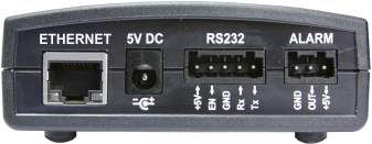
- send an e-mail when an alarm state starts or ends
- use DATALINK: display current values or download values from memory to COMET Database in your PC. Software COMET Database contains many useful tools for data analysis - graphs, tables, statistics, etc.
- simple wireless communication with Wi-Fi TP-LINK router
- third-party applications to read the actual measured values using universal protocols SNMPv1 and XML
- view current measured values using your web browser
Output ALARM OUT
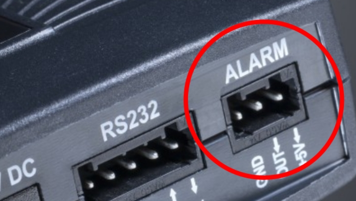
- Output can be used for controling other devices when alarm is launched, such as external buzzer, telephone dialer etc.
- Type of output - open collector transistor
- Max. switching current - 100 mA
- Max. voltage on output - 12 V
- Auxiliary voltage at terminal - +5 V (only when the mains supply is present)
- Users can receive alarms if the values go outside the paramters set. Alarms are indicated through an internal buzzer , 3 LEDs or email alerts via Ethernet port.
Reference

Measurement of runoff wastewater treatment plant
Type of application: Healthcare and Laboratory Agriculture

Cool Room temperature monitoring with MULTILOGGER
Type of application: Healthcare and Laboratory

Prague Castle
Type of application: Building Management - HVAC Server rooms and data centers Culture

Masaryk University in Brno
Type of application: Industry Building Management - HVAC Weather monitoring

Drazice farm
Type of application: Industry


